VGA from an Arduino?
Well really, I doubt you could use the Arduino IDE to make it...
I was thinking this should be possible, and if I used a shift register on the output, it should be able to produce a fairly high resolution. (As it turns out, this is exactly what they did on the ZX80 microcomputer.) There are a few other similar projects out there, but none with this kind of resolution.
What kind of resolution can we get? Let's think about the instructions required to display one glyph (8 pixels wide) on one scanline:
| Load the next character from memory | 2 |
| Load the glyph data from program memory | 3 |
| Write to the shift register | 1 |
| Enable the shift register | 1 |
| Disable the shift register | 1 |
| 8 |
As it turns out, it's one pixel per clock cycle. (I hope that there are load instructions that automatically advance the pointers.) Edit: You need a few more cycles to calculate the glyph pointer. You can avoid this by preparing the glyphs between each scanline.
Let's assume a 16MHz device. Each line is 25.17µs long. This allows 402 pixels per line, or 50 characters. The number of lines is limited more by your available RAM than anything else (one reason I put the glyphs in program memory instead of the SRAM). Clocked at 20MHz, you'll get 62 columns.
The system could be entirely interrupt driven, allowing other stuff to go on. Sure you wouldn't get maximum performance but how many AVR/Arduino apps spend most of their time in a busy wait?
The amount of RAM shouldn't be too much of a problem, since the 2k in the ATmega232 allows for 40 lines. You could get more lines or graphics effects by replacing the character memory during the screen draw. You get about 6.6 µs between lines, which is about 100 instructions, which is a fair bit of time.
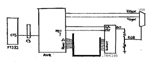
So what might the circuit look like? To write 8 pixels on 1 clock cycle, we need the shift register on a single port. Port C only has 7 lines, port B has the crystal connected to it, so that leaves only port D. The serial connection is on this port though, so if we want to use that, we'll need some kind of flow control to stop the other end sending during the screen drawing. This could be a simple XON/XOFF system, or by connecting an output to the CTS pin of the FT232 chip via the X2 connector.
The other issue with Port D is that I'd like to consider colour or brightness one day, and three of the OC outputs are on this port, including both outputs for timer 2. I think that the 16 bit timer (timer 1) could be used for both timing and colour though.
The only thing left to do is get a clock signal for the shift register. The AVR has no clock output, and you can't use the SPI clock because I think its maximum speed is half the clock frequency. Perhaps it can be connected to the crystal somehow.
The circuit would look something like this:
So why would you want this? For the "wow" most probably... but one use would be an Arduino shield that displays the status of each pin. You could sample the pins during the vertical retrace, and display them during the frame. You could display the voltages on the analogue pins, which is the advantage over using LEDs. You'd need to toggle the various ports between input and output during the retrace, so there would be a few components to isolate the pins during drawing. A few 74HC4066 switches should do. Or some diodes.
And CRT monitors are a dime a dozen, so you could connect a bunch of them together to display all sorts of stuff. Add some wireless shields (or some cheaper modules) and put synchronized screens all around the room.
You could use a similar technique to get a TV display. Add some external oscillators and you might even get some colour!