More timing video signals on the STM32L Discovery
I've looked how ChibiOS does its timing, and worked out that it's unsuitable for timing video signals. Now I'll look at the using the timers directly.
The chip has a number of timers, I can't work out how many. The ChibiOS HAL manual says it can use timers 2, 3 and 4, so let's leave those alone for other uses. That leaves timers 9, 10 and 11.
If the timers work like the AVR's timers, they work by starting at 0 and counting up to some maximum value, where the counter is reset to 0. There's also a compare register, and when the timer matches the compare register, something can happen - we can trigger an interrupt, change the state of a pin and so on. Being able to change a pin is how PWM works.
It would be nice to use PWM to produce the sync signals. I've found an excellent description of these signals, and at the start of each line, there's always a falling signal. So if we set the timer's maximum value to the end of the line, and have the signal go low when it overflows, that's the signal start taken care of.

The signal end is a bit trickier. The image shows that it varies depending on the line; further, on some of the vertical sync lines it happens twice! This means that we might need to change the value at which the signal goes high as the timer is running. The AVR can do this, but in some modes the timer register is double-buffered. If you write a new value to the timer compare register, it's only applied the next time the timer resets. They do this so you don't set a compare value lower than the current register, which means the timer will keep counting up until it overflows!
So can you adjust the compare registers on the fly on the STM32L, and is it double buffered? It looks like the compare register is called TIMx_CCR1. There doesn't seem to be a CCR2, so maybe these timers only have one output. In the reference manual, section 17.6.11 says:
It is loaded permanently if the preload feature is not selected in the TIMx_CCMR1 register (bit OC1PE). Else the preload value is copied in the active capture/compare 1 register when an update event occurs.
So if the preload feature is off, the compare register can be updated straight away! But back in the PWM mode description (section 17.4.9), it says:
You must enable the corresponding preload register by setting the OCxPE bit in the TIMx_CCMRx register
So we're not so lucky. We need to use the preload register, and we know it updates on an "update event". What's an update event? Back in section 17.4.1:
The update event is sent when the counter reaches the overflow and if the UDIS bit equals 0 in the TIMx_CR1 register.
So all we need to do is update the compare register one line early!
What about the vertical sync lines, where there are two pulses? That shouldn't be a problem; we simply consider them two separate lines in software, so the lines are numbered like this:
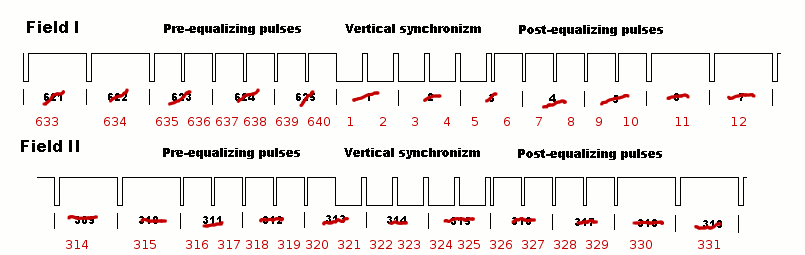
This also shows that the maximum value will need to be changed in the same way. In the reference manual, they call this value the "auto-reload" value, and it's kept in the TIMx_ARR register. Section 17.4.1 suggests you can choose whether this is double-buffered or not. We might as well use this feature since the compare register needs it.
There's one more thing to look at. At the start of each line, I'll need to start transferring data from memory to an external port using DMA, and configure the compare and maybe the maximum value register for the next line. I could either do both in a single interrupt, or set the registers on the reset interrupt, and start the DMA on the compare interrupt.
Do we have enough time from the start of the interrupt to do anything useful? The horizontal sync pulse on a PAL signal is 4.7μs. If we assume the CPU runs at 16MHz, this is about 75 instructions. Section 5.5.1 of the ARM manual suggests that it takes 12 cycles to enter an interrupt. In the AVR, it's up to the programmer to save the register state at the start of an interrupt. This means it's a good idea to do as little as possible in an interrupt, because the compiler inserts lots of "push" and "pop" instructions around the interrupt. Since the ARM looks after this for you, and takes a fixed amount of time to enter an interrupt, this isn't a problem. If we assume it takes 12 cycles to leave an interrupt too, that leaves about 50 cycles to do stuff. This stuff is working out how long it should take to raise the signal again, and set the compare register and maybe the reset register.
That should be all we need to know about the timers - now I'll try to use the timer to produce these horizontal sync pulses.