Coding PWM on the STM32L
So how about coding up the PWM to produce the hsync signal from my previous post? Here's my first attempt:
#include "ch.h"
#include "hal.h"
#include "stm32l1xx.h"

int main(void) {
  halInit();
  chSysInit();

  rccEnableAPB2(RCC_APB2ENR_TIM11EN, 0); // Enable TIM11 clock, run at SYSCLK

  // TIM11 outputs on PA7, PB9 or PB15
  GPIOB->MODER &= ~GPIO_MODER_MODER9;
  GPIOB->MODER |= GPIO_MODER_MODER9_1; // alternate function on pin B9
  TIM11->CCR1 = TIM_CR1_ARPE // buffer ARR, needed for PWM (?)
          | TIM_CR1_CEN; // counter enable... proably important!
  TIM11->CCMR1 &= ~(TIM_CCMR1_CC1S); // configure output pin
  TIM11->CCMR1 =
          TIM_CCMR1_OC1M_2 | TIM_CCMR1_OC1M_1 | TIM_CCMR1_OC1M_0  // output high on compare match
          | TIM_CCMR1_OC1PE; // preload enable
  TIM11->CCER = TIM_CCER_CC1P // active low output
          | TIM_CCER_CC1E; // enable output
  TIM11->ARR = STM32_SYSCLK * 0.000064;   // horizontal line duration
  TIM11->CCR1 = STM32_SYSCLK * 0.0000047; // hsync pulse duration

  TIM11->CR1 |= TIM_CR1_CEN; // enable the counter

  palSetPadMode(GPIOB, 7, PAL_MODE_OUTPUT_PUSHPULL);
  while (1) {
    palSetPad(GPIOB, 7);
    chThdSleepMilliseconds(500);
    palClearPad(GPIOB, 7);
    chThdSleepMilliseconds(500);
  }
}
I'll attach my DSO Nano to PB9, and... nothing! I don't think it's the DSO; that should be good to a few μs.
So why isn't it running? Maybe the timer is running, but the pin output isn't. I started OpenOCD, and attached GDB to it. The datasheet says that TIM11 is at 0x40011000, and the reference manual says the counter is at offset 0x24. With this information, I can look at the contents of the timer - the GDB manual says I can look at memory using the "x" command:
$ <strong>arm-none-eabi-gdb build/ch.elf</strong>
GNU gdb (GNU Tools for ARM Embedded Processors) 7.3.1.20120613-cvs
Copyright (C) 2011 Free Software Foundation, Inc.
License GPLv3+: GNU GPL version 3 or later <http://gnu.org/licenses/gpl.html>
This is free software: you are free to change and redistribute it.
There is NO WARRANTY, to the extent permitted by law.  Type "show copying"
and "show warranty" for details.
This GDB was configured as "--host=i686-linux-gnu --target=arm-none-eabi".
For bug reporting instructions, please see:
<http://www.gnu.org/software/gdb/bugs/>...
Reading symbols from /home/damien/projects/stm32/video/build/ch.elf...done.
(gdb) <strong>target remote :3333</strong>
Remote debugging using :3333
ResetHandler () at /opt/ChibiOS_2.4.2/os/ports/GCC/ARMCMx/crt0.c:262
262      asm volatile ("cpsid   i");
(gdb) <strong>cont</strong>
Continuing.
<strong>^C</strong>
Program received signal SIGINT, Interrupt.
0x08000588 in _idle_thread (p=<optimized out>)
at /opt/ChibiOS_2.4.2/os/kernel/src/chsys.c:62
62      chRegSetThreadName("idle");
(gdb) <strong>x 0x40011024</strong>
0x40011024:    0x000002ed
(gdb) <strong>cont</strong>
Continuing.
<strong>^C</strong>
Program received signal SIGINT, Interrupt.
0x08000588 in _idle_thread (p=<optimized out>)
at /opt/ChibiOS_2.4.2/os/kernel/src/chsys.c:62
62      chRegSetThreadName("idle");
(gdb) <strong>x 0x40011024</strong>
0x40011024:    0x0000067c
(gdb) <strong>x 0x40011024</strong>
0x40011024:    0x000005b8
(gdb) <strong>x 0x40011024</strong>
0x40011024:    0x0000050c
(gdb) <strong>x 0x40011024</strong>
0x40011024:    0x00000774
(gdb)
The value is changing - that's a good start! Note that I didn't have to continue the program to see the timer incrementing - it runs even though the debugger has stopped execution! Also, the timer never seems to set the top 4 bits, which suggests it's resetting at some value before it overflows its 16 bits. This maximum value should be 32MHz*64μs=0x800, so it's looking good.
There's an application note discussing the timers in the STM32 chips, and reading that closely it looks like I've been confusing the "output compare" mode and the PWM mode. I think in the AVR these are essentially the same, but in the STM32 there doesn't look like there's a way to reset the pin upon overflow when in output compare mode (so this mode doesn't seem to be that useful to me, apart from one-shot events). The ChibiOS PWM code is worth looking at too.
A few days have passed since I did the above bit...
I read the reference on GPIOs a bit more. I would have guessed that since I told the chip to connect to the timer, the timer would look after that pin. But after reading section 6.3.2 of the datasheet about configuring pins for the alternate function, it looks like there's a AFR register to set. Figure 18 suggests I need to set the AFRH register to "3" to enable the timer on this pin. I added these lines:
  GPIOB->AFRH &= ~GPIO_AFRH_AFRH9;
  GPIOB->AFRH |= 0x3 << 4; // ChibiOS doesn't seem to have constants for these
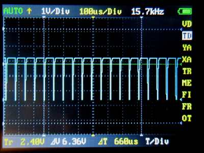
and finally I get some output! The timing looks right, but there's some strange stuff happening with the amplitude of this waveform. I'm hoping it's aliasing with my DSO, so hopefully I'll get to use a CRO in a few days to confirm this. I made the timings a bit longer, and it didn't look as bad, but maybe there's some other aliasing going on with the clocks in the chip.
Another problem is that the waveform is the wrong way around! There seem to be two settings that affect this: the OC1M bits in CCMR1, which say whether the waveform is active when the counter is less than the compare register; the other specifies the polarity of the output. Maybe I only have to change one of these? It seems odd to have two registers which do mostly the same thing. I'll change the polarity in CC1P.
That's looking better! I swapped CCER and OC1M around, and the output looked the same.
I noticed that the signal doesn't rise very quickly. Looking through the GPIO registers again, I got the OTYPER setting wrong which made it open drain. Changing this around fixed this problem.
So here's my complete code:
  rccEnableAPB2(RCC_APB2ENR_TIM11EN, 0); // Enable TIM11 clock, run at SYSCLK

  // TIM11 outputs on PA7, PB9 or PB15
  GPIOB->OTYPER &= ~GPIO_OTYPER_OT_9;        // Push-pull output
  GPIOB->OSPEEDR |= GPIO_OSPEEDER_OSPEEDR9; // 40MHz
  GPIOB->PUPDR &= ~GPIO_PUPDR_PUPDR9;
  GPIOB->PUPDR |= GPIO_PUPDR_PUPDR9_0;      // Pull-up
  GPIOB->MODER &= ~GPIO_MODER_MODER9;
  GPIOB->MODER |= GPIO_MODER_MODER9_1; // alternate function on pin B9

  // Reassign port B9
  GPIOB->AFRH &= ~GPIO_AFRH_AFRH9;
  GPIOB->AFRH |= 0x3 << 4; // ChibiOS doesn't seem to have constants for these   TIM11->CR1 |= TIM_CR1_ARPE; // buffer ARR, needed for PWM (?)
  TIM11->CCMR1 &= ~(TIM_CCMR1_CC1S); // configure output pin
  TIM11->CCMR1 =
          TIM_CCMR1_OC1M_2 | TIM_CCMR1_OC1M_1 // output high on compare match
          | TIM_CCMR1_OC1PE; // preload enable
  TIM11->CCER = TIM_CCER_CC1P // active low output
           | TIM_CCER_CC1E; // enable output
  TIM11->ARR = STM32_SYSCLK * 0.000064;   // horizontal line duration
  TIM11->CCR1 = STM32_SYSCLK * 0.0000047; // hsync pulse duration

  TIM11->CR1 |= TIM_CR1_CEN; // enable the counter
Next I need an interrupt when the signal goes low, so I can adjust the signal timings for the vertical sync.